Detailed Reference & Troubleshooting Guide
JERHEN INDUSTRIES DETAILED REFERENCE & TROUBLESHOOTING GUIDE
Our expert team of expert maintenance specialists can assist with your on-site troubleshooting and maintenance needs. For information or a quote on the repair or maintenance of your Jerhen or Warren equipment, contact us today and a member of our team will connect with you soon.
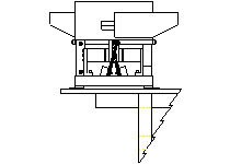
IMPROPER MOUNTING
This feeder is not properly mounted. One-half of it is off the machine. The bearing weight of two of the rubber feet is not supported, which robs the feeder of the vibration needed from the drive unit. This kind of mounting will cause loss of feed rate.
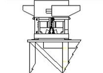
PROPER MOUNTING
This feeder is mounted properly. Note the bearing weight of all four-rubber feet is supported. There is not strain on the unit and it will stay level. The brace reinforcement to the floor provided a solid support and can be lagged to the floor. Another way to correct the mounting problem in the diagram to the left is to provide a separate table off the machine for the vibratory parts feeder. Feeders that are isolated from the machine cannot pick up counter motion from an indexing machine. If the feeder is isolated, it can be easily leveled and lagged down to ensure maximum performance.
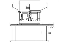
IMPROPER MOUNTING
This feeder is not mounted properly. Risers constructed of small diameter bar stock are too thin and improperly reinforced. In this example, the sub-base plate is being used as a top plate, which is not rigid enough. It may seem to be working, but the feeder cannot reach maximum performance.
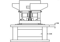
PROPER MOUNTING
This feeder is mounted properly. Due to the large dimension of the bar stock used for the riser and reinforcement, and the thick top and bottom plate, this drive unit will transfer sufficient vibration to the bowl to reach maximum performance in orienting the parts and delivering the maximum feed rate. Also note that the weight of the four rubber feet of the drive unit are well supported, which is vital to proper performance.
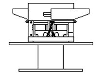
IMPROPER MOUNTING
This feeder is not mounted properly. Note the thin top and bottom plates. Also, there are no gusset reinforcements under the feet on the drive unit. The plates can flex and absorb vibration from the drive unit. A center column that is too small causes the top plate to warp, which robs the feeder of the necessary power required to function properly.
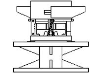
PROPER MOUNTING
This feeder is mounted properly. Note the gusset reinforcements and the thickness of the top and bottom plates. The center column is sufficient to keep the top plate from warping and reducing the possibility for insufficient power to the feeder.
PROPER MOUNTING
Each table or stand that supports a vibratory feeder must be rigid, reinforced, level, and lagged down to the floor on all four corners. This will ensure maximum performance and tends to reduce noise level. A stand should be constructed of steel or aluminum. Wooden tables or benches will absorb vibration required to reach the maximum performance.

